Electromagnetic Wave Research
Introduction
This course studies the propagation characteristics of electromagnetic waves.
It organizes the properties of electromagnetic waves, such as refraction,
reflection, spectroscopy, and the Doppler effect of light, explains the theory
of the speed of electromagnetic waves emitted from a moving source, and
considers physical phenomena on celestial bodies and the Earth.
The gist of the research is that "the speed of electromagnetic waves is the sum
of the electromagnetic propagation velocity and the moving velocity of the source."
I hope that this theory will be presented to the public and proven.
項目
1.Theory of Electromagnetic Waves
1)Properties of Electromagnetic Waves
2)Electromagnetic waves and light
3)Electromagnetic wave generation
4)Propagation Velocity
5)Electromagnetic waves from a moving source
6)Laterally moving electromagnetic waves
7)Trajectory of radiated electromagnetic waves
8)Doppler phenomenon of electromagnetic waves
9)Attenuation of electromagnetic waves and changes in frequency and wavelength
2.Movement of celestial bodies
1)Light difference
2)Optical contrast
3)Binary star orbit
4)Galactic rotation curve
5)Ring galaxy
6)Attenuation of celestial light and changes in frequency and wavelength
3.Ground observations
1)Measurement of electromagnetic wave speed on the ground
2)Michelson-Morley experiment
3)Cannon aiming
4)broadcast waves
5)GPS location measurement
6)Fiber Ring Gyro
7)Japan Standard Time (JJY)
4.verification
1)Detection of absolute stationary system
2)Measuring the speed of light in celestial bodies
5.Conclusion
1.Theory of Electromagnetic Waves
We propose a new theory based on electromagnetic wave phenomena in celestial bodies and on Earth.
1)Properties of Electromagnetic Waves
The properties of electromagnetic waves shown below are phenomena that have been observed experimentally.
(1)It is electrical energy that moves through space as magnetic and electric fields oscillate.
(2)It has no mass but has momentum.
(3)Depending on the frequency of the electromagnetic waves, they are called radio waves or light.
(4)It is permeable to vacuum, air, liquids, transparent crystals, and other materials.
(5)There are phenomena of refraction, reflection, diffusion, diffraction, and interference.
(6)The propagation speed is determined by the permittivity and permeability of the environment, and is constant at 300,000 km/s in a vacuum.
(7)Doppler effects occur when the source or the observation device is in motion.
2)Electromagnetic waves and light
Radio waves are generally invisible, but light is a type of electromagnetic wave and people can sense it due to differences in its vibration frequency.
(1)Refraction of Light
Light refracts at the interface between materials with different dielectric constants, and the mixed light splits into different wavelengths due to the different
refractive indices.
In Figure 1-1 Refraction and reflection of light, the refractive index n and
electromagnetic wave speed are determined by the magnetic permeability μ and
dielectric constant ε.
The Doppler effect can be detected by measuring changes in refractive index.
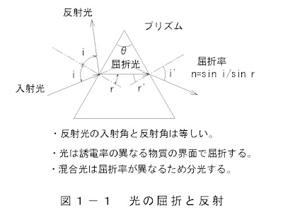 The refractive index n is expressed by the following formula:
n=sin(i)/sin(r)
(1-1)
n=(με)0.5
(1-2)
The speed of an electromagnetic wave is expressed by the following equation:
c=co/(με)0.5
(1-3)
co;Eigenvalues of electromagnetic wave speed
In a vacuum, μ=1, ε=1.
(2)Light reflection
Characteristics of light (electromagnetic waves) reflected by a mirror
- Electromagnetic waves are considered to be perfectly elastic, the angles of incidence and reflection are equal, and the motion
of the source and mirror has no effect.
-The speed of the reflected electromagnetic wave is the speed of the incident light
plus the speed of the mirror.
Figure 1-2: Light reflection. When light from a source is reflected by a mirror M, the angle of incidence and the angle of reflection
are equal regardless of the mirror's speed.
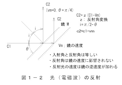 C2=z(C1-Vm) (1-4)
c2=c1+vm (1-5)
z ; Conversion of the angle of reflection, where θ is the angle between
the optical axis and the mirror.
i=π/2-θ (1-6)
c1; incident light velocity
C2; reflected light speed
Vm; Mirror movement speed
Horizontally incident light is reflected by a mirror tilted at 45 degrees
and angled 90 degrees sideways.
Figure 1-3: Speed of reflected light The speed of light reflected by the mirror is C2,
and the propagation waveform is shown.

Incident and reflected light waveforms
x=A sin((2πy/λ1)t) (1-7)
x=A sin((2πy/λ2)t) (1-8)
This becomes:
The propagation speeds C1 and C2 of electromagnetic waves are
C1=C+Vs (1-9)
C2=-(C1-Vm) (1-10)
C2=-C-Vs+Vm(1-11)
However, if the frequency ν is constant, the period is
τ1=λ1/c1 (1-12)
τ2=λ2/c2 (1-13)
となる。
3)Electromagnetic wave generation
Electromagnetic waves are generated by electrical oscillators,
and light is produced when electrons interact directly with atoms or when atoms are heated,
exciting the electrons within atoms.Electromagnetic waves are electrical energy converted
into oscillating magnetic and electric fields.When matter transforms into massless
electromagnetic waves, electrical energy is converted into vibrational energy.
Energy is expressed as E = h x ν (h: Planck's constant, ν: frequency).
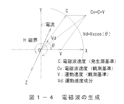
In Figure 1-4, "Generation of Electromagnetic Waves," electrons traveling in the Z-axis
direction (alternating current) create a magnetic field in the X-Y plane.
Electromagnetic waves propagate at a constant speed, with the current axis
as the origin, as a circularly radiated magnetic field generated around the current.
Furthermore, the propagating electromagnetic waves move in the direction of
the source's velocity, V. The combined velocity of the electromagnetic waves is Cv.
Note: Speed is a measure of travel between two points, i.e., distance divided by time, and
is independent of their positions (coordinates).
 Speed of electromagnetic waves
・Earth reference (observed on Earth)
Cv=C+V (1-14)
・Space standards (observations on other celestial bodies)
Cv=C+V+Ve (1-15)
・Movement speed component
Vd=V cos(θ) (1-16)
Cv ;Observed speed of electromagnetic waves
C ;Electromagnetic wave speed (source reference)
V ;Source speed (based on observation point)
Ve ;Relative velocity between Earth and other celestial bodies
Vd ;Motion velocity component
θ ;Deflection angle (the angle between the direction of electromagnetic waves and
the direction of motion)
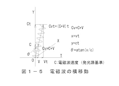
4)Electromagnetic waves traveling in the direction of movement of the source and to the side
The propagation of electromagnetic waves whose source moves laterally is
shown in Figure 1-5 Lateral Movement of Electromagnetic Waves.
As can be inferred from the previous section,
electromagnetic waves are thought to move in parallel with the movement of
the source of light.
 The waveform of an electromagnetic wave is expressed by
the following equation:
The waveform of an electromagnetic wave is expressed by
the following equation:
Stationary state
x=A sin((2π y/λ)) (1-17)
When moving to the right
x=A sin((2π y/λ))+v t (1-18)
5)5) Electromagnetic wave trajectory
The propagation state of electromagnetic waves from a moving point source
is shown in Figure 1-6:
Electromagnetic Wave Trajectory.
The source is assumed to travel to the right (X-axis) at 38% of
the electromagnetic wave speed. The deflection angle θ between
the direction of the electromagnetic wave and its motion is plotted
from 0° to 2π (360°) in increments of π/6 (30°), and the radiation
angle θ is illustrated as π/3 (60°).
The trajectory of electromagnetic waves (apparent velocity) observed
from a celestial body is the shape observed on the ground, translated
at velocity V.
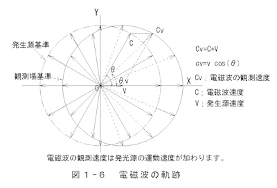
The propagation of electromagnetic waves is
Cv=C+V (1-19)
cv=(c2+v2+2c v cos(θ)) 0.5
(1-20)
θv=atan(c sin(θ)/(c cos(θ)+v)) (1-21)
It is represented by:
The apparent velocity is maximum when the deflection angle θ = 0°,
cv=c+v (1-22)
When θ is 180°, the minimum
cv=c-v (1-23)
It will be.
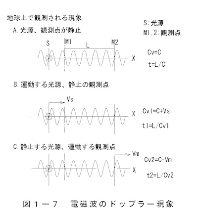
6) Doppler phenomenon of electromagnetic waves
The Doppler effect is an observed change in wavelength λ due to
the movement of either the source or the observer.
By comparing the wavelength with the original wavelength using
a wavelength measuring device (spectroscope),
we can determine the relative velocity. The change
in wavelength is equivalent when the source is moving and
when the observer is moving.
Figure 1-7, Doppler effect of electromagnetic waves,
illustrates the relationship between the movement of
the source and the observation point and the electromagnetic wave velocity.
The apparent wavelength λ is expressed by the following equation:
λ=λo c/(c+v)(1-24)
v=vs-vm (1-25)
λ、λo ; wavelength, original wavelength
c ;speed of light
v ; relative motion speed
vs,vm Source and observation point speed
The waveform shape is expressed by the following equation:
y=A sin((x+(vs-vm)t)/λ/2π)(1-26)
y ; Electromagnetic wave height
A ; wave height
x ; horizontal position
(1) Source movement and wavelength change
In Figure 1-7, when the speed of the electromagnetic wave changes, the wavelength is observed to change.
A. The source and the observation device are stationary (relative velocity is zero)
No change in wavelength is observed
y=A sin(x/λ/2π) (1-27)
B. When the light source is moving
y=A sin((x+vs t)/λ/2π)(1-28)
The electromagnetic wave speed changes and the wavelength
appears to expand and contract.
C. When the observation device is moving
y=A sin((x-vm t)/λ/2π)(1-29)
A change in the position of the observation point appears
as a change in wavelength.
(2) Explanation of parallel coordinate transformation
<reference>
In Figure 1-8 Coordinate transformation, if X and X' are
the coordinates of the celestial body and the coordinates of the Earth,
the coordinate transformation
is expressed by the following equation.
Here, L is the distance between the celestial bodies and v is
the relative velocity.
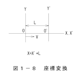
・When approaching
X=X'+L-vt (1-30)
または
X'=X-L+vt (1-31)
・When leaving
X=X'+L+vt (1-32)
または
X'=X-L-vt(1-33)
The Doppler effect occurs due to the independent movement of the light source
and the observer, or the combined movement of both, and the effect
is due to the difference in speed between the two.
Conversely, the Doppler effect can be used to determine the relative
speeds between celestial bodies.
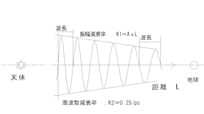
7) Attenuation of electromagnetic waves and frequency changes
So far we have discussed the basic properties of electromagnetic waves,
but we have not considered that the frequency and wavelength of electromagnetic
waves change during transmission.
From the perspective of radio engineering
1) The strength (amplitude) of radio waves attenuates in proportion
to the square of the distance d.
2) The strength of radio waves attenuates in proportion to the square of
the frequency f.
It is known that...
On the other hand, it is assumed that the frequency and wavelength
change during propagation.
In this paper, we hypothesize that "frequency and wavelength change depending
on the propagation distance."
From an energy perspective, unless there is a complete vacuum, it is
expected that the frequency will decrease and the wavelength will become
longer during propagation.
The schematic shape of this is shown in Figure 2-1-11.
If the basic waveform of an electromagnetic wave is expressed by
the following equation:
I=A sin(ωt)(1-34)
The formula that takes into account the amplitude attenuation and
the change in frequency and wavelength is
I=(1-k1t^2)A sin((1-k2t)ωo)(1-35)
k1;Amplitude attenuation rate
k2;Propagation velocity attenuation rate
It is expressed as:
The relationship between the speed of light, frequency, and
wavelength is
f=(1-k3t)fo
ω=
2πf
=2π(1-k3t)fo
=(1-k2t)ωo
k2=(1-2πf/ωo)/t
c=fλ
=(1-k3t)fo(1+k4t)λo
k3;Frequency attenuation rate
k4;Wavelength extension rate
It will be.
The speed of light c is determined by the dielectric constant ε, but
when we consider the attenuation
during transmission,
c=(1-kt)/√ελ
k=((1-k3t)fo(1+k4t)λo√ελ+1)/t
k2=(1-k3)x(1+k4)(=>1)
Also, if distance is a variable,
t=L/c(1-36)
I=(1-k1xc/L)At sin((1-k3)x(1+k4)c/L)ωo)(1-37)
can be obtained.
Although experiments and observations have not shown that
electromagnetic waves have the characteristics described above,
we will consider the background to this in the next section,
"2. Movement of Celestial Bodies."
Back to Top
2.Movement of celestial bodies
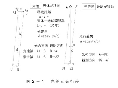
Regarding the direction in which celestial bodies are visible,
there is a principle of "optical difference" and "optical aberration"
that is associated with the movement of celestial bodies and the Earth.
The idea that "electromagnetic waves travel at a constant speed and are not affected by the movement of their source"
is known as the "constant velocity theory," and this theory is known
as the "inertial theory."
Each principle is shown in Figure 2-1: Light difference and
optical aberration.
The distance L to a celestial object is expressed in light years.
L=y [light years] (2-1)
km If we convert it to
L=c x y x 365 x 24 x 3,600[km] (2-2)
It will be.
From now on, we will omit unit conversions in the calculation formulas.
Beam angle
δ=atan(v/c)(2-3)
Beam angle
φ=atan(v/c)(2-4)
c ;Speed of electromagnetic waves (light)
v ;Velocity of motion of a celestial body or observer
y ;light years
When a celestial body moves in a straight line, the appearance of
the light difference phenomenon varies depending on the theory.
Under the fixed theory, the light appears to be in the past direction of
the celestial body, while under the inertial theory, the light appears
to be in the current position of the celestial body. In the case of
a rotating celestial body, the electromagnetic waves themselves are
fixed (fixed theory) or move in a straight line (inertial theory),
so the apparent position deviates from the celestial body's rotational
orbit. When observing nearby celestial bodies, the speed of light
propagation is so fast that no difference is noticeable, but
distant celestial bodies do have an effect.
Aberration is a phenomenon that occurs due to the movement of
the Earth, and results in an angular difference between the
direction of light and the direction it appears.
When we see the sun rising, we are looking at the sun as it was
about 8 minutes ago, but since the sun is not moving, it is
in the direction we see it.
(1)Light difference
Optical difference represents the difference in the propagation
time of light between celestial bodies. Propagation time is
the length of the path measured in terms of the speed of light.
However, how it appears is determined by the propagation path,
and since the propagation paths are different between
the "constant velocity theory" and the "inertial theory,
" the appearance will be different.
A. Light difference due to constant velocity theory
The principle is shown in Figure 2-2. A celestial body at A1, t1 moves
to A2, t2 at a speed of V. Light emitted at A1 reaches B, t2
at a speed of C.
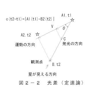
light difference equation
c(t2-t1)=|A1(t1)-B2(t2)|(2-5)
Light difference
τ=t2-t1 (2-6)
c;Speed of electromagnetic waves
A1,t1;The point and time of electromagnetic wave generation
A2,t2;Arrival point and time of celestial object
B,t2;Observation point and arrival time
Based on the idea that the movement of celestial bodies does not
affect the propagation of electromagnetic waves,
observer B2 sees the celestial body in the direction of A1 at time t2.
B. Light difference due to the theory of inertia
a. The difference in light between celestial bodies moving in a straight line
The light difference according to this theory is shown in Figure 2-3.
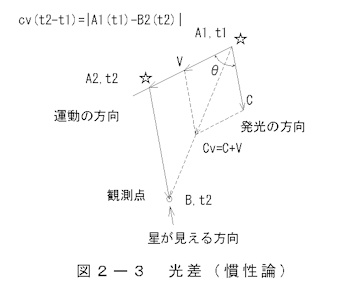
light difference equation
cv(t2-t1)=|A1(t1)-B2(t2)| (2-7)
Light difference
τ=t2-t1 (2-8)
Apparent speed
Cv=C+V (2-9)
cv=c+vcos(θ) (2-10)
V;The speed of a celestial body
Electromagnetic wave C generated at A1, t1 follows
a trajectory with an apparent velocity of Cv,
and is seen in the direction of A2, t2 at observation point B2, t2.
In other words, a virtual image of the light emitted at A1 appears at A2.
b. The difference in brightness of a rotating celestial body
The difference in brightness of light from a rotating celestial body
is shown in Figure 2-4.
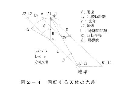
Ly=v y(2-11)
L=c y (2-12)
θ=Ly/R (2-13)
light difference equation, light difference
cv(t2-t1)=|A1(t1)-A2(t2)|(2-14)
τ=t2-t1;(2-15)
cv=c+vcos(θ)(2-16)
cv;Apparent speed of electromagnetic waves
v ;The speed of a celestial body
θ ;declination
The line of sight light generated at A1 travels toward B'
and reaches B,t2 y years later at a resultant velocity of Cv,
where it is observed on Earth. At that time, the celestial
object is located at the star on the arc.
(2) Optical aberration
Aberration is a phenomenon that occurs when an observer is moving. Electromagnetic waves propagate along a fixed path, but as the observer moves, the path appears to be tilted. If the Earth's speed relative to the Sun is 30 km/s, and the speed of light is 300,000 km/s, then the direction of a celestial object will be tilted by an angle of aberration of approximately 20 inches toward the Earth's direction of travel.
(3) Observation of orbiting galaxies
(1) As mentioned in the section on light difference, the actual
and apparent positions of celestial objects moving in a straight
line are the same, but the light traveling in the line of sight
of an orbiting galaxy moves in the direction of the circumferential
velocity of the rotation. Light traveling in the line of sight of
a galaxy moving laterally deviates from its position over time.
As a result, distant galaxies appear to have an expanded diameter.
Also, tilted galaxies appear to have a larger flattened ellipse.
This principle is shown in Figure 2-5, Lateral Movement of
Line-of-Sight Light.
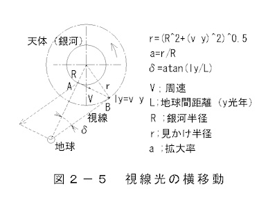
x component of rotational speed
vx=v cos(θ)(2-15)
y component of rotational speed
vy=v sin(θ) (2-16)
x component of propagation distance
ldx=vx yl (2-17)
y component of propagation distance
ldy=vy yl (2-18)
Observed galactic radius
r=(R2+ldx2+ly2) 0.5
(2-19)
A. Observation from in front of the orbital plane
The expansion of the galaxy's diameter is shown in Figure 2-6:
Observed diameter of the galaxy.
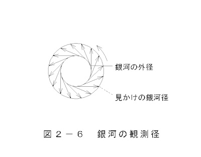
Calculate the apparent size and oblateness of a galaxy assuming
a standard galaxy.
galactic radius R=10Ten thousand light years
Rotational speed v=80km/s
Distance to the galaxy yl=5,000Ten thousand light years, 100 million light years,
500 million light years, 2 billion light years, 10 billion light years
Galaxy Magnification
a=r/R (2-20)
B. Observation from the side of the orbital plane
The speed and position of the sideways movement of binary stars
and galaxies relative to the line of sight of light as they orbit
are shown in Figure 2-7 Side view of a rotating celestial body.
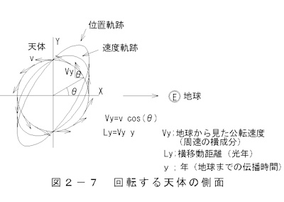 This shows two binary stars orbiting each other. The orbital velocity vy and
lateral displacement lyd are shown as seen from Earth to the right. Distance
traveled is calculated by multiplying the velocity by the travel time ly to Earth.
The inclination of the galactic plane is 45° relative to the line-of-sight plane.
This shows two binary stars orbiting each other. The orbital velocity vy and
lateral displacement lyd are shown as seen from Earth to the right. Distance
traveled is calculated by multiplying the velocity by the travel time ly to Earth.
The inclination of the galactic plane is 45° relative to the line-of-sight plane.
The position trajectory is a plot of the lateral movement distance.
| distance | 50 million light years | 100 million light years | 500 million light years | 2 billion light years | 10 billion light years |
| Magnification | 1.01 | 1.04 | 1.80 | 6.05 | 29.83 |
| Oblateness | 0.70 | 0.68 | 0.39 | 0.12 | 0.02 |
Galaxies less than 100 million light-years away don't change much in size, but galaxies further away appear to expand. It's hard to believe, but a galaxy 10 billion light-years away appears to expand by about 30 times. It's thought that this expansion phenomenon is the reason why galaxies at the edge of the universe, said to be 13.8 billion light-years away, can be observed with space telescopes. While tilted galaxies have an elliptical shape, they appear more exaggerated than they actually are. Many distant galaxies appear to have a bow-like shape. This is interpreted as "deformation due to gravitational lensing," but the true reason remains unknown.
(4) The movement of binary stars
It is said that "the speed of light propagation is constant" based on the observation of the orbital motion
of binary stars, but is this actually the case?
We will consider how the effects of the radial and counter-radial
velocities of orbiting binary stars A and B are observed.
For a sufficiently distant binary star, the difference in the time
it takes for the light from stars A and B to reach
Earth is many times the orbital period. This multiple is called the
"overlap number."
In Figure 2-8, Superposition of Binary Stars, the speed of light
in the line of
sight as viewed from the side of the binary star system
from Earth is ca = c + v,
and the speed of light in the opposite direction is cb = c - v.
Therefore, the difference in the speed of light propagation is 2V.
If the distance to Earth is ly (light years),
the separation ld occurring over y years is 2vy.
The distance propagated over half the orbital period P is cp/2.
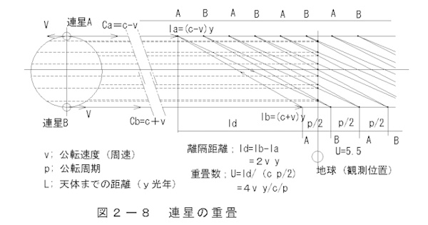
Calculating the number of overlapping binary stars
Difference in operating (rotational) speed
vd=2v(2-21)
separation distance
ld=lb-la(2-22)
=2vy(2-23)
Propagation distance for one cycle
lp=cp (2-23)
Number of overlaps
(Multiplication of the propagation distance difference ld
to the propagation distance lp of 1/2 period)
U=ld/lp (2-24)
=4vy/C/P(2-25)
v Orbital speed
C ;speed of light
ly ;light years
P ;Orbital period
Table 2-1 Introduction to representative binary stars
(Science Chronology 2008)
| Visual binary stars | spectroscopic binary star | |||||||||
| Binary star A,B | Alpha Canis Majoris | Gamma Virgo | Antares | Gemini Castor | Hercules | Centaurus | Small Magellanic Cloud | Spica | Perseus | Gemini |
| αCMa | γVir | αSco | αGem | HerX-1 | CenX-3 | SMC X-1 | αVir | βPerAB | α2Gem | |
| light year y (year) | 50 | 171 | 878 | 51 | 19,560 | 23,080 | 195,600 | 350 | 80 | 50 |
| Period P (days) | 18,250 | 62,415 | 320,470 | 2.93 | 1.70 | 2.10 | 3.90 | 6.02 | 5.02 | 4.02 |
| Circumferential speed V Km/s | 23.7 | 11.7 | 3.7 | 31.9 | 135 | 415 | 299 | 120 | 121 | 122 |
| Number of overlaps U | 2.7E-05 | 4.2E-06 | 3.8E-06 | 1.4 | 3781.4 | 11113.9 | 36526.7 | 25.5 | 4.7 | 2.5 |
Visual binaries have an overlap ratio of almost zero,
meaning they can be observed literally as they are.
Spectroscopic binaries with a small overlap ratio have
recently been identified as multiple binaries using space
telescopes. On the other hand, precise spectral observations
have revealed that binaries with a large overlap ratio are binary stars
rotating at high speeds with short periods.
What does the extremely short orbital period of a spectroscopic binary
star mean? We can think of it as two binary stars appearing as multiple stars.
There are binary stars called pulsars, which are hundreds of millions of
light-years away. In such cases, the number of overlaps is exponential,
and the spectrum is thought to be pulsed. As a result, the motion of
the binary star causes changes in the propagation speed of light.
The more distant the binary star, the greater the effect.
(5) Galactic rotation curve
Observing the rotation speed of galaxies allows us to verify the propagation
characteristics of electromagnetic waves. The observed rotation curve of
galaxies deviates from Kepler's laws. We will elucidate the reason for
this based on the "propagation characteristics
of electromagnetic waves."
The rotation speed of a galaxy follows Kepler's laws. Light emitted
from a galaxy travels vast distances, taking tens of millions or even
billions of years to reach us, so the observed shape of the galaxy is
not its current form. The deformation of the galaxy's rotation curve is
calculated by applying the "theory of inertia of electromagnetic waves.
" For the formula for calculating the propagation of electromagnetic waves
(light), see the previous section,
"2) Light Difference."
The speed of an electromagnetic wave is the combination of the velocity v
of the light source and the inherent speed c
of the electromagnetic wave.
Electromagnetic waves are treated as vectors that are the result of
the motion of the light source and the propagation of light.
A. Overview of the Galactic Rotation Curve
Figure 5-1 shows an overview of the galactic rotation curve.
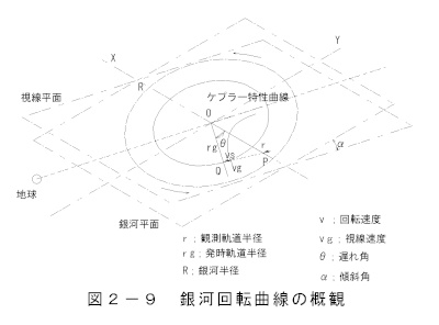 The illustration shows the galaxy from above on the right.
The line-of-sight plane is inclined by an angle α with respect
to the galactic plane.
Let the distance from the galaxy to Earth be y light years,
and the maximum radius of the galaxy be R light years.
Let the distance from the galaxy to Earth be y light years, and the maximum radius of
the galaxy be R light years.
The rotation speed of the galaxy follows Keplerian properties.
Let the angle through which the galaxy rotates during the delay time
of light transmission
between the galaxy and the Earth be the delay angle θ.
The component perpendicular to the radius of rotation that emits light at Q arrives
at point P after y years.
The light in the line of sight direction is the delay
angle θ direction component.
The coordinates of the galactic rotation plane rotate clockwise
by a delay angle θ relative to the line-of-sight plane.
On the other hand, the line-of-sight velocity vs is perpendicular to the radius r.
The speed of light emitting at point Q, vg, follows the Kepler property.
In conclusion, the light emitted from Q in the line of sight direction
is observed at P. When observing from Earth, we correct for the tilt angle
α between the line of sight plane and the galactic plane.
B. Calculating the Galactic Curve
The actual propagation speed is C + v, but the speed of light c is
omitted in the calculation.
Figure 5-2 is a detailed explanation of the rotation curve.
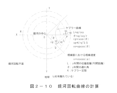 ・Delay angle
L=vg/cxy(2-26)
θ=vg/cxy/r(2-27)
Keplerian properties
rg=rxcos(θ)(2-28)
vg=K/rg^0.5 (2-29)
・Galaxy radial velocity
vs=vgxcos(θ)(2-30)
・Line-of-sight velocity
v=vsxcos(α)(2-31)
L;y annual propagation distance (distance between P and Q)
θ; y-year delay angle
The formula for the galactic radius rg and the delay angle
θ is an approximate calculation. There will be an error at the center of rotation,
but it does not affect the quality.
C. Rotation curve graph
The calculation results are shown in Figure 2-11, a galactic rotation curve graph.
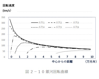
The vertical axis is the rotation speed (km/s)
The horizontal axis is the galactic radius (10,000 light-years)
Graph 1-6 series shows the following characteristics.
Series 1: Keplerian properties
Series 2; 1 million light years
Series 3: 3 million light years
Series 4: 10 million light years
Series 5: 30 million light years
Series 6; 100 million light years
The rotation curves of nearby galaxies, such as the Milky Way
(100,000-200,000 light-years) and the Andromeda Galaxy (2.3 million light-years),
exhibit Keplerian properties, but they appear distorted due to the large
influence of the delay angle in distant galaxies. No light is observed
at the centers of distant galaxies, where the delay angle exceeds π/2
(90 degrees). The formula assumes a constant Keplerian coefficient, but
in reality, Keplerian properties are thought to change radially.
6) Ring galaxies
Many circular rings have been observed. As mentioned in section
(3) Observations of Orbiting Galaxies, the radial velocity
of a galaxy relative to Earth varies depending on its distance
from Earth and its radius.
Figures 2-12-1 and -2 are graphs of observed galactic radii,
with radius as a parameter on the vertical axis and distance
to Earth on the horizontal axis.
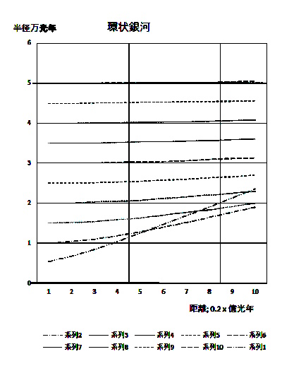
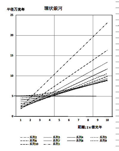
Distance to Earth
0.2-2 bilion light years
2-20 billion light years
Figure 1 shows the distance between Earth and the galaxy
at 0.2-2 billion light years, while Figure 2 shows the distance
between Earth and the galaxy at 2-20 billion light years.
At distances of less than 2 billion years, the galaxy appears
as it is, but at around 6-12 bilion light years, the inner
and outer lines of sight intersect (switch). At radii of more
than 12 billion light years, the actual and apparent radii are
completely reversed, and the galaxy appears donut-shaped.
7) Attenuation and wavelength change of light from celestial bodies
Changes in the shape of electromagnetic waves affect astronomical observations, but the propagation distance is not actually taken into account.It is believed that the state and appearance of celestial bodies change as light propagates.
As discussed in theory, the following phenomenon occurs when the frequency of light decreases.
The frequency decreases with distance, so the light from a distant star shifts towards the red side.
Also, since luminous intensity decreases in proportion to the square of the distance, there is a limit to the visible range.
In real observations
1) The universe appears to be expanding.
2) The edge of the universe is thought to be 13.8 billion light years away.
However, those observations would be incorrect.
The Hubble constant and the rate of frequency decrease can be expressed as follows:
Frequency attenuation rate
Dr=Ho/c (2-32)
=73.2/(3*10^8)/Mpc (2-33)
=0.24/pC (2-34)
Furthermore, the theory of the expanding universe is unnatural for the following reasons:
1) The Earth is not the center of the universe.
2) What is the force that accelerates celestial bodies?
3) The expansion speed of celestial bodies at the edge of the universe exceeds the speed of light.
Even if it is impossible to verify the facts, it is necessary to be convinced theoretically.
The intensity of electromagnetic waves (light) attenuates over distance, and the frequency decreases, so there is a limit to the distance they can travel and they disappear. Therefore, "space, or the night sky, is dark."
Back to Top
3. Phenomena observed on the ground
When an electric current crosses a magnetic field, a force is generated in the conductor. This is a reaction that occurs when a moving electric current generates a magnetic field. The movement of an antenna emitting electromagnetic waves generates a force on the antenna, just as the movement of a conductor carrying a high-frequency current does. In other words, the moving antenna current gives momentum to the electromagnetic waves. If electromagnetic waves traveling sideways from the direction of their source were left behind by the principle of the "constant speed of light," problems would occur. Meanwhile, the effect of the source's speed on the traveling speed of electromagnetic waves is negligible, but it does affect speed guns and analog television receivers.
1) Measurement of electromagnetic wave speed on the ground
The speed of light is defined as 299,792,458 ± 1.2 m/s, calculated by multiplying the frequency and wavelength of a He-Ne laser. Because the wavelength is measured using the principle of optical interference, it is not affected by the Earth's orbital speed or the speed of the solar system. If the speed of electromagnetic waves changes, assuming the Earth's speed is 200 km/s, the error would be 1.3 x 10E-6, so its effect cannot be ignored. Although it is said that "the speed of light is constant, regardless of the motion of the light source," this has not been proven by observation. Furthermore, the definition of "constant speed" is vague, and it is necessary to explain forward speed and lateral motion.
4) Michelson-Morley experiment
The Michelson-Morley experiment was conducted under the assumption that interference fringes would appear due to the difference in the optical path speeds of two light beams emitted from a light source on the moving Earth, but no interference phenomenon occurred. In this experiment, the light source and detector moved at a constant speed, so there was no change in wavelength and therefore no interference fringes appeared.
4) Elementary particle collision experiments
The basis for the statement that "the speed of electromagnetic waves is constant" is that "there is no difference in the speed of the υ mesons generated by electron collisions." However, since the source, beryllium, is stationary, the electromagnetic waves generated have no speed of motion.
1) Cannon aiming
A battleship's cannon can aim at a target 40 km away. If the Earth's motion caused a 1/2,000 error in the aiming calculation, the target would be 20 m at 40 km, but this is not true. The Earth's motion does not affect the calculation of the cannon's aiming.
2) Propagation of broadcast waves
Television and radio broadcast waves are not affected by the Earth's motion at all. If radar observation equipment and microwave transmissions were affected by the Earth's motion, modern society would not exist.
3) Measurement of the rotation speed of the fiber ring gyro
A fiber ring gyro transmits light in a fiberglass coil in both left and right directions, measuring the time difference with an interferometer. Because the device is attached to a moving object, the light travels in parallel with the object, so the speed of light is the same in both directions and is unrelated to the movement of the Earth or the universe. The difference in the light's travel time is proportional to the rotation angle of the moving object. Incidentally, the travel distance of the moving object is calculated as L = V x t
3) Distance measurement in GPS
The propagation time of radio waves used to calculate the distance between a satellite and the ground should be calculated using the apparent speed of electromagnetic waves. In reality, calculations using the speed of electromagnetic waves result in errors, but these are considered to be other errors.
4) Japan Standard Time (JJY)
Standard time transmitting stations are located in Saga Prefecture and Fukushima Prefecture. Research has shown that the waveforms received from these stations, 60 Hz and 40 Hz standard time radio waves, exhibit phase shifts over a 12-hour cycle. This is thought to be due to the Earth's rotational speed affecting the radio waves transmitting high-precision information.
Back to Top
4.検証
The propagation of electromagnetic waves is a mixture of theoretical and traditional beliefs. Anything that remains uncertain should be clarified through measurement and experimentation. To know the true speed of electromagnetic waves, we could measure the speed of light coming from celestial bodies, but this requires ingenuity and effort. It seems possible to measure the speed of electromagnetic waves using particle experiment equipment.
1) Detection of absolute stationary system
Let's think about the meaning of a stationary frame. Stationary means that an object is still, so the space known as the universe cannot be defined; it is neither static nor moving. However, we can imagine a state in which an object is "absolutely stationary." However, considering that the Earth on which we live orbits the sun, the sun is in a galaxy, and that the galaxy is also moving, it is natural to think that stationary celestial bodies do not exist.
2) Measurement of the apparent speed of electromagnetic waves from celestial bodies
Observing the Doppler effect indirectly measures the speed of light,
but is there a way to directly measure the apparent speed of
electromagnetic waves?
It is possible to measure the apparent speed of light by measuring the transit
time of electromagnetic waves coming from space.
Furthermore, while it seems possible in principle to use Foucault's historic
measuring device, is it possible to build such a device?
KAGURA recently began operation, and this may hold promise.
Aren't the edge of the universe different from the limit of observation?
Furthermore, it would be extremely arrogant to assume that the beginning
of the universe is the same as the limit of observation.
Isn't this human-centered science? So I ask again: "Is the Earth the center
of the universe?"
5. Conclusion
A long time has passed since the idea for this paper was conceived, but
personally, due to time constraints, I consider this research to be
the "definitive version."
A conclusion may not be reached quickly, but I hope that it will be
clarified someday. I would like to hear the opinions and criticisms
of many researchers.
Osamu Terai
E-Mail;terais@jcom.home.ne.jp